the12volt.com spacer
icon

Viper 5706V With Omegalink Bypass Module, 2007 Nissan Titan


Post ReplyPost New Topic
< Prev Topic Next Topic >
desert islander 
Member - Posts: 15
Member spacespace
Joined: September 04, 2024
Location: California, United States
Posted: September 12, 2024 at 10:02 PM / IP Logged Link to Post Post Reply Quote desert islander
Hey Lee, you mentioned above to be sure to connect the red, red/white and red/black fused wires.
The viper wiring diagram shows the red/black fused wire connects to the accessory/starter input, the red fused wire connects to ignition 1 input and the red/white fused wire connects to ignition 2/flex relay input 87. According to the wiring diagram for my Titan there isn't an ignition 2 input.
desertislandertech
lee.lopez 
Member - Posts: 17
Member spacespace
Joined: September 02, 2024
Location: Texas, United States
Posted: September 13, 2024 at 2:00 PM / IP Logged Link to Post Post Reply Quote lee.lopez
It's a little confusing how Viper words the manual. All the red fused wires connect to constant 12 volt power. When it says ignition 2 input, it just means it's the power to feed the internal circuit, which you are reprogramming to Starter 2.
desert islander 
Member - Posts: 15
Member spacespace
Joined: September 04, 2024
Location: California, United States
Posted: September 14, 2024 at 12:15 AM / IP Logged Link to Post Post Reply Quote desert islander
The Viper diagram has one wire on the 6-pin main harness connector that specifically shows to connect the red 12v constant input to a constant 12v circuit at the ignition. Are you saying that this 12v constant wire connects with all the other three fused wires together from the 10-pin heavy gauge connector even if the diagram shows that the red/black fused wire connects to the accessory/starter input, the red fused wire connects to ignition 1 input and the red/white fused wire connects to ignition 2/flex relay input 87?
desertislandertech
lee.lopez 
Member - Posts: 17
Member spacespace
Joined: September 02, 2024
Location: Texas, United States
Posted: September 14, 2024 at 3:15 AM / IP Logged Link to Post Post Reply Quote lee.lopez
The quick start guide you have is more of a reference for installers that are familiar with Viper systems, so it doesn't go into that much detail.
Yes, I'm saying they all need to be connected to constant 12 volts, which is why they are all fused. The thick fused wires provide power to the relays that are built into the Viper. These relays connect to the starter, accessory and ignition wires. What I've often done is connected the red wire in the main harness to one of the fat red wires in the remote start harness.
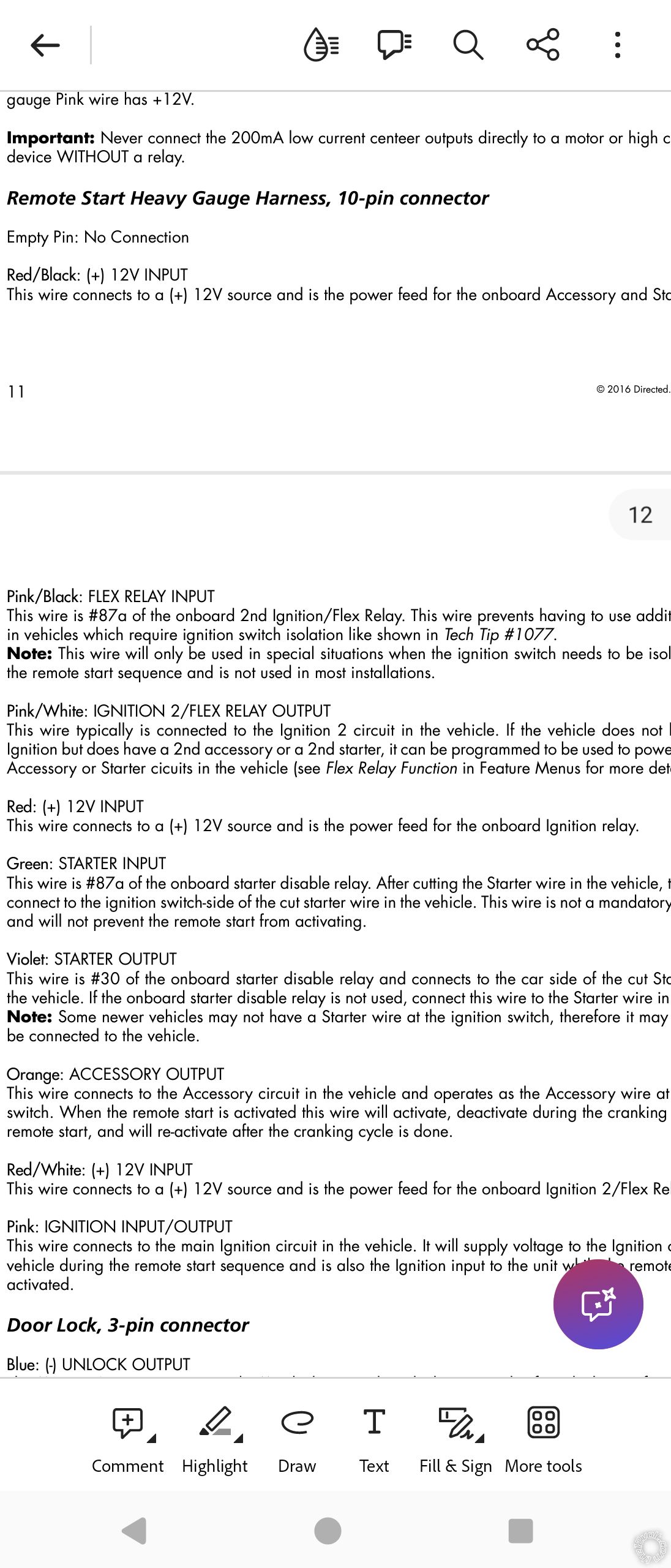
See pages 11 and 12 of the complete installation manual. Here's the link again in case you haven't downloaded it: https://www.the12volt.com/installbay/file.asp?ID=1341
You'll see that the red/black wire provides power to the starter. If you do not connect this wire to constant 12 volts you will not be able to remote start because it is the power source for the Viper's on board starter relay. The red/white wire provides power to the flex relay (which is ignition 2 by default). Notice this wire is labeled as #87 which is the normally open contact on a standard 12 volt automotive relay.
Viper 5706V With Omegalink Bypass Module, 2007 Nissan Titan - Page 2 -- posted image.
desert islander 
Member - Posts: 15
Member spacespace
Joined: September 04, 2024
Location: California, United States
Posted: September 14, 2024 at 11:27 AM / IP Logged Link to Post Post Reply Quote desert islander
Okay I got it. Now on the RS 10-pin heavy gauge harness there is the pink/black (+) flex relay input 87A key side (if require) of flex relay. Where does this connect to?
This is from the link you sent.
Pink/Black: FLEX RELAY INPUT
This wire is #87a of the onboard 2nd Ignition/Flex Relay. This wire prevents having to use additional relays in vehicles which require ignition switch isolation like shown in Tech Tip #1077.
Note: This wire will only be used in special situations when the ignition switch needs to be isolated during the remote start sequence and is not used in most installations.
desertislandertech
lee.lopez 
Member - Posts: 17
Member spacespace
Joined: September 02, 2024
Location: Texas, United States
Posted: September 14, 2024 at 1:08 PM / IP Logged Link to Post Post Reply Quote lee.lopez
Not used in your setup. You can tape it off or remove it from the harness if you want.
desert islander 
Member - Posts: 15
Member spacespace
Joined: September 04, 2024
Location: California, United States
Posted: September 15, 2024 at 4:15 PM / IP Logged Link to Post Post Reply Quote desert islander
On RS 6-pin main harness parking light output will connect to parking light positive red/blue at electric brake harness pre-wiring harness (white 6-pin plug) pin-4, is this correct?
desertislandertech
lee.lopez 
Member - Posts: 17
Member spacespace
Joined: September 02, 2024
Location: Texas, United States
Posted: September 15, 2024 at 5:00 PM / IP Logged Link to Post Post Reply Quote lee.lopez
Yes, that's what I'm seeing. You can verify with a multimeter.
One more thing- make sure you program for automatic transmission (manual is default).
desert islander 
Member - Posts: 15
Member spacespace
Joined: September 04, 2024
Location: California, United States
Posted: September 15, 2024 at 9:28 PM / IP Logged Link to Post Post Reply Quote desert islander
Will do thanks for catching that.
desertislandertech
desert islander 
Member - Posts: 15
Member spacespace
Joined: September 04, 2024
Location: California, United States
Posted: September 18, 2024 at 11:52 AM / IP Logged Link to Post Post Reply Quote desert islander
I have a hood pin for this installation. There is a gray (-) hood pin input (NC or NO) on the RS 24-pin Auxiliary/shutdown/trigger. Will I need this wire for the hood pin if connecting D2D?
desertislandertech
Page of 3

  Printable version Printable version Post ReplyPost New Topic
You cannot post new topics in this forum
You cannot reply to topics in this forum
You cannot delete your posts in this forum
You cannot edit your posts in this forum
You cannot create polls in this forum
You cannot vote in polls in this forum

  •  
Search the12volt.com
Follow the12volt.com Follow the12volt.com on Facebook
Sunday, September 22, 2024 • Copyright © 1999-2024 the12volt.com, All Rights Reserved Privacy Policy & Use of Cookies
Disclaimer: *All information on this site ( the12volt.com ) is provided "as is" without any warranty of any kind, either expressed or implied, including but not limited to fitness for a particular use. Any user assumes the entire risk as to the accuracy and use of this information. Please verify all wire colors and diagrams before applying any information.

Secured by Sectigo
the12volt.com spacer
Support the12volt.com
Top
the12volt.com spacer