the12volt.com spacer
icon

Viper 5706V With Omegalink Bypass Module, 2007 Nissan Titan


Post ReplyPost New Topic
< Prev Topic Next Topic >
lee.lopez 
Copper - Posts: 67
Copper spacespace
Joined: September 02, 2024
Location: Texas, United States
Posted: October 19, 2024 at 8:08 PM / IP Logged Link to Post Post Reply Quote lee.lopez
You mentioned no starter output but have power on accessory. That means the fuse on the red/black wire is good.
Sounds like the starter output on the Viper is bad. Check the fuse on the red/white wire.
When you try to remote start, you can jump power to the starter wire and see if it starts and runs. If it does, you can try using the negative starter output wire (purple/yellow pin 21) to trigger a relay and connect the output to the vehicle starter wire.
desert islander 
Member - Posts: 35
Member spacespace
Joined: September 04, 2024
Location: California, United States
Posted: October 20, 2024 at 1:16 PM / IP Logged Link to Post Post Reply Quote desert islander
30-amp fuse is good on red/white. This wire is labeled as 12-volt constant power feed for the onboard ignition 2/flex relay input.
What do you mean by jumping power to the stater wire and where do I jump it from?
Could I jump from the 12-volt constant, or do I need to get this from somewhere else?
If this does work, do I need a separate relay or could I use the onboard relay to trigger the starter wire assuming the car side purple wire?
I also still have not figured out the lock/unlock for the viper key fob. It still doesn't work. Only work for alarm arm/disarm function.
desertislandertech
lee.lopez 
Copper - Posts: 67
Copper spacespace
Joined: September 02, 2024
Location: Texas, United States
Posted: October 20, 2024 at 1:58 PM / IP Logged Link to Post Post Reply Quote lee.lopez
Yes, you could jump it from constant or ignition power, but only momentarily. This is just a test. If it starts and runs, then see if the negative starter output will trigger a relay.
Yes, you would use a separate relay.
Have you tried the wires at the power window switch?
desert islander 
Member - Posts: 35
Member spacespace
Joined: September 04, 2024
Location: California, United States
Posted: October 20, 2024 at 3:30 PM / IP Logged Link to Post Post Reply Quote desert islander
Ok I will try that but can I leave the starter kill purple connected while performing this test? Is there no way to use the onboard relay and programming this in menu?
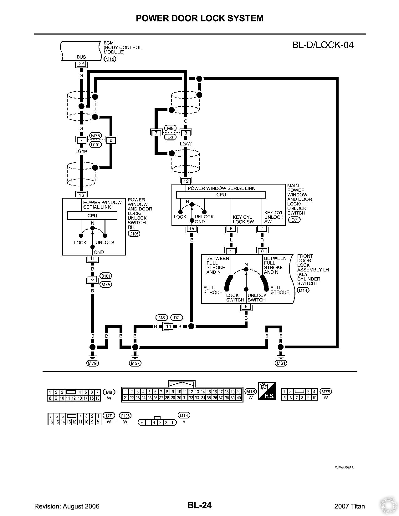
I'm still trying find the correct wires at the door. I checked the 16-pin connector at the window switch but can't seem to identify the correct wires. The wiring diagram says to check the power lock Blue (type b) pin 6 or 4 and power unlock Red (type B) pin 7 or 6 and requires a double pulse. I'm not sure what type B means though. Note for both says to test these wires while turning the key in the drivers door and that this will
arm and disarm the factory alarm. I tested all wires at the connector and none of them show any change.
desertislandertech
lee.lopez 
Copper - Posts: 67
Copper spacespace
Joined: September 02, 2024
Location: Texas, United States
Posted: October 20, 2024 at 4:31 PM / IP Logged Link to Post Post Reply Quote lee.lopez
This is just a test to see if it will work. Leave the wiring as is for now. If you're not getting an output from the Viper, how do you plan to use the onboard relay? Since this is a DIY system, it's not like you can swap out the unit for a replacement. You need to either work around it or buy another one.
If it doesn't work you can still add starter kill: https://www.the12volt.com/relays/relaydiagram10.html
Type B is negative switched. Connect your red meter lead to a constant 12 volt source. Connect your black lead to your test wire. Set your meter to read DC volts. Turn and hold the key in the driver door while watching the reading. The wire that gives you a normal reading at 0 volts and only reads 12 volts when you turn the key is the one you want.
desert islander 
Member - Posts: 35
Member spacespace
Joined: September 04, 2024
Location: California, United States
Posted: October 20, 2024 at 4:48 PM / IP Logged Link to Post Post Reply Quote desert islander
Got it. Hopefully this works.
Going to test the door wires. Thanks for making this test easier to understand.
desertislandertech
desert islander 
Member - Posts: 35
Member spacespace
Joined: September 04, 2024
Location: California, United States
Posted: October 22, 2024 at 9:34 PM / IP Logged Link to Post Post Reply Quote desert islander
I haven't had the chance to perform the starter jump test.
I was able to test the door lock wires. I found the lock/unlock wires but when I put the red lead from the MM to a 12-volt source and the black lead to the lock/unlock wires it tested 6.8 volts before turning the key and 11.8 volts when turning the key. This test is the same for both lock pin-4 and unlock pin-6.
Viper 5706V With Omegalink Bypass Module, 2007 Nissan Titan - Page 6 -- posted image.
desertislandertech
lee.lopez 
Copper - Posts: 67
Copper spacespace
Joined: September 02, 2024
Location: Texas, United States
Posted: October 22, 2024 at 9:51 PM / IP Logged Link to Post Post Reply Quote lee.lopez
Perfect, you found your lock wires then. I realize I said they will show 0 volts, but this is not necessarily the case. A 5 volt system like yours would show a difference of around 7 volts (your 6.8 volt reading) and then 12 volts (11.8 volts) when you turn the key.
Page of 6

If you wish to post a reply to this topic, you must first login.
If you are not already registered, you must first register.

  Printable version Printable version Post ReplyPost New Topic
You cannot post new topics in this forum
You cannot reply to topics in this forum
You cannot delete your posts in this forum
You cannot edit your posts in this forum
You cannot create polls in this forum
You cannot vote in polls in this forum

  •  
Search the12volt.com
Follow the12volt.com Follow the12volt.com on Facebook
Wednesday, October 23, 2024 • Copyright © 1999-2024 the12volt.com, All Rights Reserved Privacy Policy & Use of Cookies
Disclaimer: *All information on this site ( the12volt.com ) is provided "as is" without any warranty of any kind, either expressed or implied, including but not limited to fitness for a particular use. Any user assumes the entire risk as to the accuracy and use of this information. Please verify all wire colors and diagrams before applying any information.

Secured by Sectigo
the12volt.com spacer
Support the12volt.com
Top
the12volt.com spacer