the12volt.com spacer
icon

is it safe additional accessory diagram


Post ReplyPost New Topic
< Prev Topic Next Topic >
tetracleric 
Member - Posts: 9
Member spacespace
Joined: April 24, 2007
Location: United States
Posted: April 27, 2007 at 9:48 AM / IP Logged  
Theres another reason for going with a dual relay setup. The single relay method means I have to run long wires from the trunk to the front of my car for the switches. The dual relay method allows me to keep shorter runs. As the only wire going to the back is the first blue wire. It's just easier than trying to fish more wire under my carpet.
as for the diode on the coil of the relay. that was reccomended by various places to prevent some kindof backfire voltage. Just dont know if I have the orientation of it right.
KPierson 
Platinum - Posts: 3,527
Platinum spaceThis member consistently provides reliable informationspace
Joined: April 14, 2005
Location: Ohio, United States
Posted: April 27, 2007 at 10:14 AM / IP Logged  

The orientation is correct, but like I said, they arn't needed.  The backflow of voltage is caused by the magnetic field of the coil collapsing.  This back voltage can damage sensitive components, but won't affect your battery in any way.

The two relays won't hurt anything, I just see them as beeing unneeded (KISS).  You are already running a decent sized power wire to the back of the car, so adding one or two 20 guage wires isn't going to be a big hassle.  What is the idea behind have an 'on/off' switch and a 'kill' switch?  They are both doing the exact same thing.  Are you just installing them in different locations for convenience?

Kevin Pierson
tetracleric 
Member - Posts: 9
Member spacespace
Joined: April 24, 2007
Location: United States
Posted: April 27, 2007 at 10:37 AM / IP Logged  
KPierson wrote:

The orientation is correct, but like I said, they arn't needed.  The backflow of voltage is caused by the magnetic field of the coil collapsing.  This back voltage can damage sensitive components, but won't affect your battery in any way.

The two relays won't hurt anything, I just see them as beeing unneeded (KISS).  You are already running a decent sized power wire to the back of the car, so adding one or two 20 guage wires isn't going to be a big hassle.  What is the idea behind have an 'on/off' switch and a 'kill' switch?  They are both doing the exact same thing.  Are you just installing them in different locations for convenience?

Nope, one forces the ignition line going to the back to stay active even if I turn the car off.
The other forcefully turns off the line going to the back. this switch will be hidden. It's more of a "mechanics" switch where if my cars getting service done I flip this switch so they cant access my carpc/system. It will probably be a key switch inside the glovebox or center console armrest.
dualsport 
Silver - Posts: 983
Silver spacespace
Joined: September 27, 2005
Location: United States
Posted: April 27, 2007 at 9:32 PM / IP Logged  
Why would it be any different with the number of wires running to the trunk if you use the single relay setup? A simple isolation diode will do the same thing as the extra relay.
Wherever you were planning on putting that relay, you just connect a diode, it can be in the exactly the same location, and doesn't even need the extra ground connection needed for the relay.
Possibly the confusion here is that you're thinking the extra "second" relay we're referring to is the one in the trunk. What we're suggesting here is to get rid of the "first" relay.
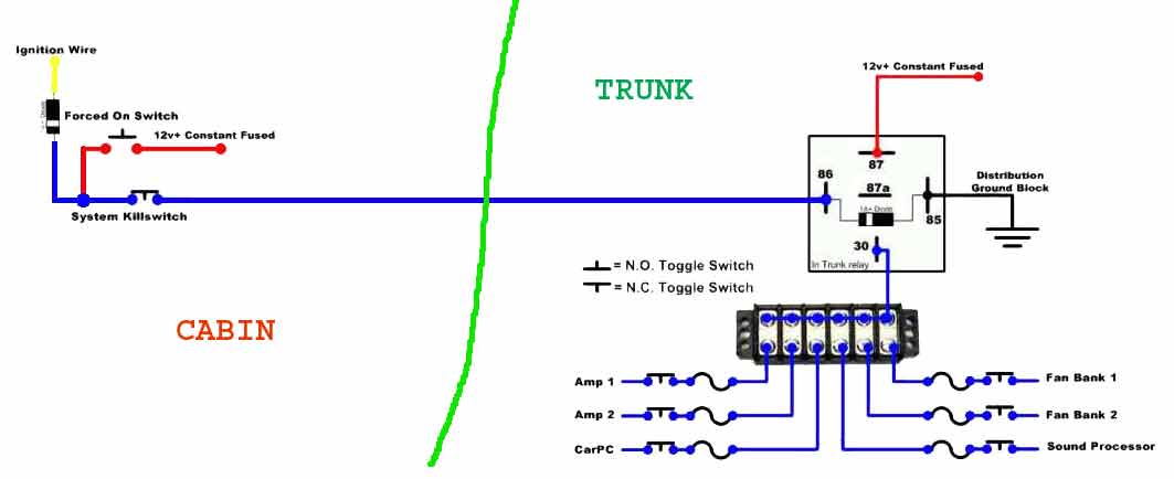
If you just want to use up the extra relays you have laying around, then that's another matter- is it safe additional accessory diagram - Page 2 -- posted image.
tetracleric 
Member - Posts: 9
Member spacespace
Joined: April 24, 2007
Location: United States
Posted: April 27, 2007 at 10:24 PM / IP Logged  
dualsport wrote:
Why would it be any different with the number of wires running to the trunk if you use the single relay setup? A simple isolation diode will do the same thing as the extra relay.
Wherever you were planning on putting that relay, you just connect a diode, it can be in the exactly the same location, and doesn't even need the extra ground connection needed for the relay.
Possibly the confusion here is that you're thinking the extra "second" relay we're referring to is the one in the trunk. What we're suggesting here is to get rid of the "first" relay.
If you just want to use up the extra relays you have laying around, then that's another matter- is it safe additional accessory diagram - Page 2 -- posted image.
The problem is the switches have to be in the cabin. I already have relay 2 setup in the trunk, its not going anywhere.
In order to allow the killswitch and the bypass switch to work from the drivers seat i'd have to run 4 wires from that rear relay to the cabin, thats more wirework that I just dont want to do.
I know you're talking about getting rid of the first relay. But that relay allows me to have shorter wire runs, less work(I dont have any wire fishers, so pulling wire under carpet with the seats still installed is a pain.
Theres already an ignition wire that runs into the back of the car from the dash. On top of that I can use the power and ground off the old unused radio harness. If I do the dual relay setup then my switches from from the dash to where I want them. Saves me cable and time. In the end its actually less work to go with the dual relays than the single.
Also like I said I do have like 90 relays laying around, so it would e nice to use them.
dualsport 
Silver - Posts: 983
Silver spacespace
Joined: September 27, 2005
Location: United States
Posted: April 28, 2007 at 7:37 AM / IP Logged  
What are the four wires you're saying need to be run from the rear relay to the cabin? I only see the same one wire, exactly the same as if you were to use the additional first relay. I can't see the problem here-
Maybe stretching out the wires in the drawing makes it clearer.
is it safe additional accessory diagram - Page 2 -- posted image.
Does that help?
tetracleric 
Member - Posts: 9
Member spacespace
Joined: April 24, 2007
Location: United States
Posted: April 29, 2007 at 10:33 PM / IP Logged  
yes that clears it up, for some reason i couldnt get my head around the connection properly.
Wired it into my car today. Couldnt find my butane soldering iron so I used a crimp connection. when it comes time to redo it(After i finish my dash fabrication) I'll make the connections more solid.
dualsport 
Silver - Posts: 983
Silver spacespace
Joined: September 27, 2005
Location: United States
Posted: April 29, 2007 at 11:49 PM / IP Logged  
Good deal-
You might consider adding a 1A fuse at the connection between the ignition switch line and your switch line, just to protect the ignition circuit if the long switch wire happens to short to ground somewhere along the run. The diode probably would pop first, but it's safer using a fuse to be sure.
That actually might be a good excuse for using your extra relay, to convert your ignition signal to a ground switched signal, so you can control your relay in the trunk with a ground (-) signal instead of a 12V (+) signal. If the long wire shorted out, worst thing that would happen is the trunk relay would turn on. No worries about fuses or wire meltdown. The extra relay in the front would only be energized when the ignition is on, so you don't have any extra standby current drain to worry about.
If you want to do this:
-Replace your 12V+ Constant Fused input with a ground
-Substitute for the diode: a relay that turns on with the ignition and switches a ground connection output.
-Connect term. 85 on the trunk relay to term 87 (+12V constant) instead of ground
-Remove the diode from the trunk relay (or at least reverse the polarity if you still want to use it)
Page of 2

Sorry, you can NOT post a reply.
This topic is closed.

  Printable version Printable version Post ReplyPost New Topic
You cannot post new topics in this forum
You cannot reply to topics in this forum
You cannot delete your posts in this forum
You cannot edit your posts in this forum
You cannot create polls in this forum
You cannot vote in polls in this forum

  •  
Search the12volt.com
Follow the12volt.com Follow the12volt.com on Facebook
Friday, September 20, 2024 • Copyright © 1999-2024 the12volt.com, All Rights Reserved Privacy Policy & Use of Cookies
Disclaimer: *All information on this site ( the12volt.com ) is provided "as is" without any warranty of any kind, either expressed or implied, including but not limited to fitness for a particular use. Any user assumes the entire risk as to the accuracy and use of this information. Please verify all wire colors and diagrams before applying any information.

Secured by Sectigo
the12volt.com spacer
Support the12volt.com
Top
the12volt.com spacer