the12volt.com spacer
icon

1996 ford bronco factory keyless entry?


Post ReplyPost New Topic
< Prev Topic Next Topic >
Ween 
Platinum - Posts: 1,366
Platinum spacespace
Joined: August 01, 2004
Location: Illinois, United States
Posted: February 03, 2013 at 2:00 PM / IP Logged  
so for door lock use pink / YELLOW C242 pin 4, door unlock pink/green C242 pin 5, horn dark blue C240 pin 26...all are negative trigger. for parking lights use brown C240 pin 24, door trigger BLACK/ light blue C242 pin 7 or 19...these are positive polarity.
1966fskbk 
Member - Posts: 23
Member spacespace
Joined: February 02, 2013
Location: Washington, United States
Posted: February 03, 2013 at 3:41 PM / IP Logged  
Your all the freaken BEST! Im going to give it a shot this afternoon.... I do have a nice digital multi-meter as well, this is going to be fun with all your help. Thank you !!!
Mike
CloudCasters
kreg357 
Platinum - Posts: 7,800
Platinum spaceThis member has made a donation to the12volt.com. Click here for more info.spaceThis member has been recognized as an authority in Electrical Theory. Click here for more info.spaceThis member has been recognized as an authority in Mobile Security and Convenience. Click here for more info.spacespace
Joined: January 30, 2009
Location: Pennsylvania, United States
Posted: February 03, 2013 at 3:54 PM / IP Logged  

Hi Mike,

To test for a (-) type wire like Lock or Unlock, set your DMM to 20V DC, connect the Red test lead to +12V constant ( battery ) and the Black test lead to the suspect wire.  DMM will indicate +12V when signal is present.

To test for a (+) type wire like Parking Lights, set your DMM to 20V DC and connect the Black test lead to chassis ground and the Red test lead to the suspect wire.  DMM will indicate +12V when signal is present.

Have fun with the DMM!   1996 ford bronco factory keyless entry? - Page 2 -- posted image.

Soldering is fun!
1966fskbk 
Member - Posts: 23
Member spacespace
Joined: February 02, 2013
Location: Washington, United States
Posted: February 03, 2013 at 5:17 PM / IP Logged  
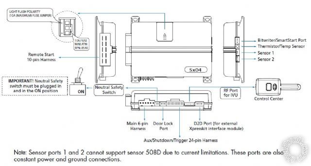
Here is what I found online and I have the 520.4x:
Responder LE Models
Viper 5204
Clifford 520.4X
Python 524
Security and Remote Start
Installation Guide
Main Harness (H1), 6-pin connector
H1/1 RED (+)12VDC CONSTANT INPUT
H1/2 BLACK (-) CHASSIS GROUND
H1/3 BROWN (+) SIREN OUTPUT
H1/4 WHITE/ BROWN PARKING LIGHT ISOLATION WIRE - PIN 87a of onboard relay
H1/5 WHITE PARKING LIGHT OUTPUT
H1/6 ORANGE (-) 500mA GROUND WHEN ARMED OUTPUT
H2 Harness, 24-pin connector
H2/1 PINK/WHITE (-) 200mA IGNITION/FLEX RELAY CONTROL OUTPUT
H2/2 BLACK/ WHITE (-) NEUTRAL SAFETY INPUT
H2/3 BLUE/WHITE (-) 200mA 2ND STATUS /REAR DEFOGGER OUTPUT
H2/4 GREEN/ BLACK (-) 200mA OEM ALARM DISARM OUTPUT
H2/5 RED / WHITE (-) 200mA TRUNK RELEASE OUTPUT
H2/6 GREEN (-) DOOR TRIGGER INPUT (N/C* OR N/O)
H2/7 BLACK / YELLOW (-) 200mA DOME LIGHT SUPERVISION OUTPUT
H2/8 BROWN / BLACK (-) 200mA HORN HONK OUTPUT
H2/9 DARK BLUE (-) 200mA STATUS OUTPUT
H2/10 PINK (-) 200mA IGNITION 1 OUTPUT
H2/11 WHITE/ BLACK (-) 200mA AUX 3 OUTPUT
H2/12 VIOLET (+) DOOR TRIGGER INPUT
H2/13 WHITE/ VIOLET (-) 200mA AUX 1 OUTPUT
H2/14 VIOLET/BLACK (-) 200mA AUX 2 OUTPUT
H2/15 ORANGE / BLACK (-) 200mA AUX 4 OUTPUT
H2/16 BROWN (+) BRAKE SHUTDOWN INPUT
H2/17 GREY (-) HOOD PIN INPUT (N/C OR N/O)
H2/18 VIOLET / YELLOW (-) 200mA STARTER OUTPUT
H2/19 BLUE (-) TRUNK PIN/ INSTANT TRIGGER INPUT (N/C OR N/O)
H2/20 GREY/BLACK (-) DIESEL WAIT TO START INPUT
H2/21 WHITE/ BLUE (-) REMOTE START/ TURBO TIMER ACTIVATION INPUT
H2/22 ORANGE (-) 200mA ACCESSORY OUTPUT
H2/23 VIOLET/WHITE TACHOMETER INPUT
H2/24 GREEN / WHITE (-) 200mA OEM ALARM ARM OUTPUT
*The Normally Closed setting will only work if one of the vehicle's doors is connected. If more than one door
is to be monitored, then it is recommended to use the Xpresskit DTIMAZDA or tech tip # 1921 on www.directechs.
com to interface with these types of vehicles.
Remote Start, (H3) 10-pin connector
H3/1 PINK (+) IGNITION 1 INPUT/OUTPUT
H3/2 RED / WHITE (87) FLEX RELAY +12V INPUT (30A FUSED)
H3/3 ORANGE (+) ACCESSORY OUTPUT
H3/4 VIOLET (+) STARTER OUTPUT (CAR SIDE OF THE STARTER KILL)
H3/5 GREEN (+) STARTER INPUT (KEY SIDE OF THE STARTER KILL)
H3/6 RED IGNITION 1 +12V INPUT (30A FUSED)
H3/7 PINK/WHITE (30) FLEX RELAY OUTPUT (car side of ign, acc or starter wire)
H3/8 PINK/BLACK (87a) FLEX RELAY INPUT (key side of ign, acc or starter wire if needed)
H3/9 RED / BLACK ACCESSORY/STARTER RELAY +12V INPUT (30A FUSED)
H3/10 NC No Connection
Door Lock, 3-pin connector
1 BLUE (-) 500mA UNLOCK OUTPUT
2 EMPTY NOT USED
3 GREEN (-) 500mA LOCK OUTPUT
CloudCasters
1966fskbk 
Member - Posts: 23
Member spacespace
Joined: February 02, 2013
Location: Washington, United States
Posted: February 03, 2013 at 5:20 PM / IP Logged  
Here is the unit: Clifford 520.4x
1996 ford bronco factory keyless entry? - Page 2 -- posted image.
CloudCasters
1966fskbk 
Member - Posts: 23
Member spacespace
Joined: February 02, 2013
Location: Washington, United States
Posted: February 03, 2013 at 5:29 PM / IP Logged  
Here is what I think goes where with the help I have received. Please tell me if Im on the right track.
so for door lock use pink / YELLOW C242 pin 4,
(3 PIN - Green)
door unlock pink/green C242 pin 5,
(3 PIN - BLUE)
horn dark blue C240 pin 26...all are negative trigger.
(H2/8 - Brn/Blk)
for parking lights use brown C240 pin 24,
(H1/5 - White)
door trigger BLACK/ light blue C242 pin 7 or 19...these are positive polarity.
(H2/6 - Green)
Am I right?? :)
CloudCasters
1966fskbk 
Member - Posts: 23
Member spacespace
Joined: February 02, 2013
Location: Washington, United States
Posted: February 03, 2013 at 5:41 PM / IP Logged  
Getting the power:
I think I'm not wanting to grab the constant 12v from steering column. I think I will go the extra and grab dedicated 12v constant from the battery post and run it in through firewall (neatly and in a harness of course). I also was thinking of placing an inline fuse a couple inches from post connection? Good? What size fuse?
Thanks All!!!
CloudCasters
Ween 
Platinum - Posts: 1,366
Platinum spacespace
Joined: August 01, 2004
Location: Illinois, United States
Posted: February 03, 2013 at 6:02 PM / IP Logged  
switch your door trigger to H2/12 (purple) as the bronco has positive triggered door switches.
for H1/1 (red), use a 20 amp fuse on 14 gauge wire, the fuse is there to protect the wire.
if you do do remote start functions, it is fine to use the wiring at the ignition switch/steering column.
1966fskbk 
Member - Posts: 23
Member spacespace
Joined: February 02, 2013
Location: Washington, United States
Posted: February 04, 2013 at 1:49 AM / IP Logged  

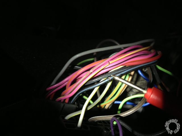
All wires and testing instructions on how to confirm using a DMM have proven exact. Here are some photos for how its going.

I will spread the gaps on the factory wires a bit more (where the testing tap areas are) and then twist my wires into the spots, solder them then tape them.  After completed I will use black 3m wire loom and zip tie shut to hide the attachments.

I will do remote starter part tomorrow.  Also mounted siren in motor compartment area pointed down and where it will not get wet.

CloudCasters
1966fskbk 
Member - Posts: 23
Member spacespace
Joined: February 02, 2013
Location: Washington, United States
Posted: February 04, 2013 at 1:58 AM / IP Logged  

1996 ford bronco factory keyless entry? - Page 2 -- posted image.

CloudCasters
Page of 5

  Printable version Printable version Post ReplyPost New Topic
You cannot post new topics in this forum
You cannot reply to topics in this forum
You cannot delete your posts in this forum
You cannot edit your posts in this forum
You cannot create polls in this forum
You cannot vote in polls in this forum

  •  
Search the12volt.com
Follow the12volt.com Follow the12volt.com on Facebook
Friday, September 20, 2024 • Copyright © 1999-2024 the12volt.com, All Rights Reserved Privacy Policy & Use of Cookies
Disclaimer: *All information on this site ( the12volt.com ) is provided "as is" without any warranty of any kind, either expressed or implied, including but not limited to fitness for a particular use. Any user assumes the entire risk as to the accuracy and use of this information. Please verify all wire colors and diagrams before applying any information.

Secured by Sectigo
the12volt.com spacer
Support the12volt.com
Top
the12volt.com spacer