the12volt.com spacer
icon

1996 ford bronco factory keyless entry?


Post ReplyPost New Topic
< Prev Topic Next Topic >
1966fskbk 
Member - Posts: 23
Member spacespace
Joined: February 02, 2013
Location: Washington, United States
Posted: February 05, 2013 at 5:33 PM / IP Logged  
Here is my next "started" plan to connect for Remote Site H3 I am missing some things I think need double checking please:
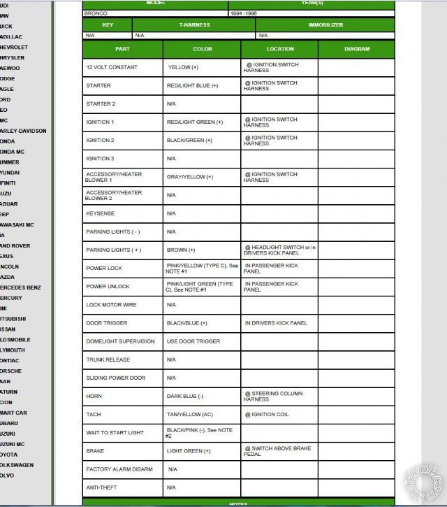
ALL BOLD next to harness connection - is the 1996 Ford Bronco color I am planning to use, I got this data from the bulldog security diag site - I will post its location next.
Remote Start, (H3) 10-pin connector
H3/1 PINK (+) IGNITION 1 INPUT/OUTPUT Ignition Harness - RED / Light Green (+)
H3/2 RED / WHITE (87) FLEX RELAY +12V INPUT (30A FUSED) not used ?
H3/3 ORANGE (+) ACCESSORY OUTPUT not used
H3/4 VIOLET (+) STARTER OUTPUT (CAR SIDE OF THE STARTER KILL)have no idea ??
H3/5 GREEN (+) STARTER INPUT (KEY SIDE OF THE STARTER KILL) Ignition Harness RED / Light Blue (+)
H3/6 RED IGNITION 1 +12V INPUT (30A FUSED) Ignition Harness RED / Light Green (+)
H3/7 PINK/WHITE (30) FLEX RELAY OUTPUT (car side of ign, acc or starter wire)not used ?
H3/8 PINK/BLACK (87a) FLEX RELAY INPUT (key side of ign, acc or starter wire if needed) not used ?
H3/9 RED / BLACK ACCESSORY/STARTER RELAY +12V INPUT (30A FUSED) not used ?
H3/10 NC No Connection definitely not used :) - GOT THIS ONE RIGHT FOR SURE!!!
Thanks for the help!!!! I think Im in the home stretch.. a
fter I get it all in - when do I get to add the 12v contant and grnd to the unit?
1996 ford bronco factory keyless entry? - Page 3 -- posted image.
CloudCasters
Ween 
Platinum - Posts: 1,366
Platinum spacespace
Joined: August 01, 2004
Location: Illinois, United States
Posted: February 05, 2013 at 6:45 PM / IP Logged  
H3/1..RED / light green, H3/2..yellow, H3/3..grey / YELLOW, H3/4..RED / light blue(cut this wire connect to vehicle side of wire), H3/5..RED / light blue(ignition switch side of wire), H3/6..yellow, H3/7..BLACK/ light green, H3/8..NC, H3/9..yellow, H3/10..NC. connect each of the red wires(striped or not) to a yellow at the ignition switch. those are all battery power. the green and purple are the in and out for the starter interrupt, which is why the wire is cut(interrupted). all that is left are ignition 1, 2 and accessory.
1966fskbk 
Member - Posts: 23
Member spacespace
Joined: February 02, 2013
Location: Washington, United States
Posted: February 05, 2013 at 9:56 PM / IP Logged  

If I may - this is how I interpret it and I have 1 small question  - THANKS WEEN!

H3/1..RED / light green,

H3/2..yellow,
H3/3..grey / YELLOW,
H3/4..RED / light blue(cut this wire connect to vehicle side of wire),
H3/5..RED / light blue(ignition switch side of wire),
H3/6..yellow,
H3/7..BLACK/ light green,
H3/8..NC,
H3/9..yellow,
H3/10..NC.

Step 1:

Connect each of the red wires(striped or not) to a yellow at the ignition switch. Those are all battery power.  [B]  (Question - can I connect all these all off a direct 10 guage (30 amp fused) run direct from battery post?  Or better yet to a small distribution block then all 12v contants from the alarm (red wires)  to it?  [/B]

Step 2:

The green and purple are the in and out for the starter interrupt, which is why the wire is cut(interrupted).

Step 3:

All that is left are ignition 1, 2 and accessory.

CloudCasters
kreg357 
Platinum - Posts: 7,800
Platinum spaceThis member has made a donation to the12volt.com. Click here for more info.spaceThis member has been recognized as an authority in Electrical Theory. Click here for more info.spaceThis member has been recognized as an authority in Mobile Security and Convenience. Click here for more info.spacespace
Joined: January 30, 2009
Location: Pennsylvania, United States
Posted: February 05, 2013 at 10:37 PM / IP Logged  

I would connect the R/S +12V power wires to individual Yellow wires.  Keep everything short and inside the vehicle.

Test the ignition wires carefully.  There should be 5 Yellow +12V constant wires.  You might find something like this.

Ignition1      RED / Light GREEN..........Powers Ignition Coil (Primary Ignition).
Ignition2      GRAY / YELLOW..........Powers ABS Module.  18 Ga
ACC1 BLACK/ Light GREEN........Powers Heat/AC Controls.
ACC2 GRAY / YELLOW (2)......Powers Blower Motor.  ** 2 Of The 3 GRAY / YELLOW Wires Listed Are The Same Circuit.
Starter          RED / Light Blue

If you need to power an extra ACC circuit, use a 30/40 Amp SPDT relay and wire as follows :

Relay Pin 85 to Viper (-) 200mA Orange Accessory Output
Relay Pin 86 and 87 to +12V constant ( another Yellow wire ) fused at 30 Amps
Relay Pin 30 to ACC2 @ ignition switch harness
Relay Pin 87A not used - insulate

Soldering is fun!
Ween 
Platinum - Posts: 1,366
Platinum spacespace
Joined: August 01, 2004
Location: Illinois, United States
Posted: February 05, 2013 at 10:41 PM / IP Logged  
a single 30A fuse won't be enough, it would probably blow when a high blower speed is selected. ford shows 2 50A feeds as well as a 20A feed to the ignition switch. one of the 50A feeds supplies the RED / light green and BLACK/ light green, while the other supplies the grey / YELLOW.
the grey / YELLOW is actually two grey / YELLOWs which feeds the blower motor circuit. the 20A feed supplies a third grey / YELLOW (thinner) as well as the RED / light blue. the 50A fuses are numbered 15 and 17, the 20A, 10. i believe the thin grey / YELLOW not listed needs to be powered up. more to follow.
Ween 
Platinum - Posts: 1,366
Platinum spacespace
Joined: August 01, 2004
Location: Illinois, United States
Posted: February 05, 2013 at 11:02 PM / IP Logged  
thanks kreg for the input...now if it was my vehicle i would revise the H3 connections. H3/1,2,4,5,6 remain the same. H3/3 to thin grey / YELLOW, H3/7 to grey / YELLOW, H3/9 to thin yellow.
a relay would be used for the BLACK/ light green. relay connections, term 30 to yellow (same one powering H3/6), term 87 to BLACK/ light green, term 87a not used, term 86 to thin grey / YELLOW, term 85 to H2/9 (status output). but each installer has their methods for wiring additional relays
1966fskbk 
Member - Posts: 23
Member spacespace
Joined: February 02, 2013
Location: Washington, United States
Posted: February 06, 2013 at 12:41 PM / IP Logged  

Hi All,

So am I reading a relay is required? 

And

The color code being refered as BLACK/ light green is actualy BLACK/ green yes?  I do not see a BLACK/ light green.

Question:

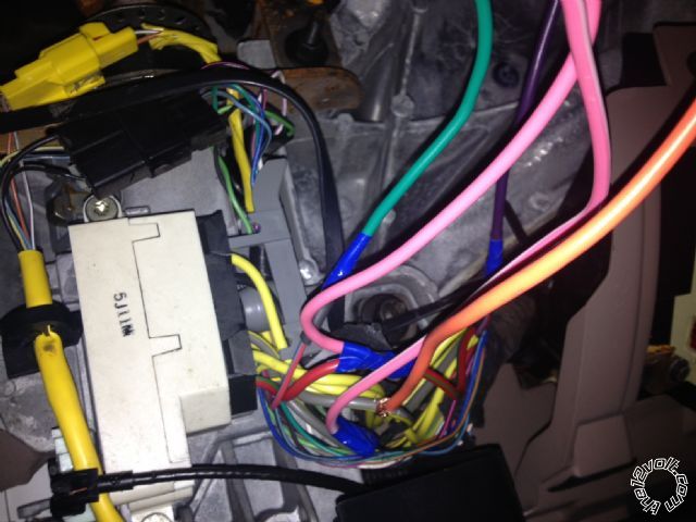
All cables are soldered that are taped up, I will put everything in a harness when done.  I temporaily tied all reds together for testing purposes to one power source, and will tie them in to the Yellows as suggested for sure once everything is confirmed.  There is three grey / YELLOWs with one being thinner at ignition.  I have tied my orange temporarily to one of the (fat ones) but car won't start.  What am I missing ...

Here is my photo.  I do hear stuff clicking ... like in the Alarm brain area ... but should I be doing something with the fuse in that little compartment door on the alarm?  Program the remotes or something for the start part to work?

Can I hook into the dome light to get it to turn on and off when it unlocks and locks?  Do I hook that in as well at the Keyless Entry wireing?

Thanks!  (almost there!!)

Oh yeah - doors lock and alarm arms nicely.1996 ford bronco factory keyless entry? - Page 3 -- posted image.

CloudCasters
kreg357 
Platinum - Posts: 7,800
Platinum spaceThis member has made a donation to the12volt.com. Click here for more info.spaceThis member has been recognized as an authority in Electrical Theory. Click here for more info.spaceThis member has been recognized as an authority in Mobile Security and Convenience. Click here for more info.spacespace
Joined: January 30, 2009
Location: Pennsylvania, United States
Posted: February 06, 2013 at 6:13 PM / IP Logged  

There are some programming changes necessary for the Viper. 

Have you changed to Auto Trans Mode yet?

Have you changed to Tach Mode, connected the Vipers Tach Input wire to a good tach source and done a successful tach learn?

Have you connected the Neutral Safety wire to chassis ground, plugged in the Neutral Safety Switch and turned it to ON?

The jumper/fuse inside the Viper should be set to (+) and the Vipers Parking Light Output wire should be connected to the Bronco's Brown (+) Parking Light wire.

When you do get it to start, gently touch a finger to that lone H3 +12V constant input wire to see how hot it gets ( watch for melting insulation, etc ).  1996 ford bronco factory keyless entry? - Page 3 -- posted image.

Soldering is fun!
1966fskbk 
Member - Posts: 23
Member spacespace
Joined: February 02, 2013
Location: Washington, United States
Posted: February 06, 2013 at 6:33 PM / IP Logged  

Holy crud ... no to all the above.  hmmm. 

Do you guys confirm this setup requrires a relay?

Is Viper the model of Alarm you are refering - Mine is a Clifford - same?

Thanks!

I will go home and put it all in place ...

Thanks!

CloudCasters
kreg357 
Platinum - Posts: 7,800
Platinum spaceThis member has made a donation to the12volt.com. Click here for more info.spaceThis member has been recognized as an authority in Electrical Theory. Click here for more info.spaceThis member has been recognized as an authority in Mobile Security and Convenience. Click here for more info.spacespace
Joined: January 30, 2009
Location: Pennsylvania, United States
Posted: February 06, 2013 at 7:27 PM / IP Logged  

Yes, current Viper, Clifford are all similar Directed products.

As for the extra relay to power all the ignition circuits...  The jury is out on that one. 

While it is not always absolutely necessary to power all the ignition wires for a successful remote start, depending on the vehicle, strange things can happen if you don't.  It could be something simple like the heat AC fans don't come on or the power windows don't work while under remote start.     It can be more serious with ABS or Engine Check Lights.  Some  GM vehicles can incur transmission damage if the White Ignition2 wire is not powered.   Anyway some installers like to save time / money by powering the bare minimum circuits.  Other do it that way because they don't want the radio on or the wipers to come on during remote start.  Some figure it's safer to install it to work exactly like a normal key start would and power everything.

Bottom line, the choice is yours.  As Ween noted, all these circuits are high current draw circuits, so you don't want to try to use one Clifford output wire to power two vehicle circuits ( hence the relay ).

Soldering is fun!
Page of 5

  Printable version Printable version Post ReplyPost New Topic
You cannot post new topics in this forum
You cannot reply to topics in this forum
You cannot delete your posts in this forum
You cannot edit your posts in this forum
You cannot create polls in this forum
You cannot vote in polls in this forum

  •  
Search the12volt.com
Follow the12volt.com Follow the12volt.com on Facebook
Friday, September 20, 2024 • Copyright © 1999-2024 the12volt.com, All Rights Reserved Privacy Policy & Use of Cookies
Disclaimer: *All information on this site ( the12volt.com ) is provided "as is" without any warranty of any kind, either expressed or implied, including but not limited to fitness for a particular use. Any user assumes the entire risk as to the accuracy and use of this information. Please verify all wire colors and diagrams before applying any information.

Secured by Sectigo
the12volt.com spacer
Support the12volt.com
Top
the12volt.com spacer