the12volt.com spacer
icon

1996 ford bronco factory keyless entry?


Post ReplyPost New Topic
< Prev Topic Next Topic >
1966fskbk 
Member - Posts: 23
Member spacespace
Joined: February 02, 2013
Location: Washington, United States
Posted: February 08, 2013 at 2:56 PM / IP Logged  

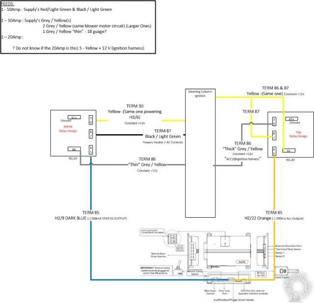
So here are the two relay designs.  I do not understand why they are so different - thanks for the help understanding why one or the other...

Clearly:

One is using a STATUS output (alarm side)?

One is using the Thick vs Thin Grey / Yellow?

One is tyine 2 terminals to a single Yellow?

One is getting power from the BLACK/ Light Green?

One is using the ACC output (alarm side)?

1996 ford bronco factory keyless entry? - Page 4 -- posted image.

CloudCasters
kreg357 
Platinum - Posts: 7,800
Platinum spaceThis member has made a donation to the12volt.com. Click here for more info.spaceThis member has been recognized as an authority in Electrical Theory. Click here for more info.spaceThis member has been recognized as an authority in Mobile Security and Convenience. Click here for more info.spacespace
Joined: January 30, 2009
Location: Pennsylvania, United States
Posted: February 08, 2013 at 3:42 PM / IP Logged  

Ok, have some confusion going on.  Obviously, you want to test all these wires with a DMM prior to making

the actual connections.  The below chart is made ASSUMING that the Ready Remote info for your 1996 Bronco
is accurate.  (Please note that there are many ways to wire up the extra relay to provide an extra high current
Accessory output for the Bronco's ignition harness.  Every installer has their own favorite way to do it.)

Remote Start, (H3) 10-pin connector

H3/1 PINK (+) IGNITION 1           RED / Light Green (+)  @ Bronco ignition switch harness
H3/2 RED / WHITE  +12V INPUT (30A FUSED) Yellow #1  @ Bronco ignition switch harness
H3/3 ORANGE (+) ACCESSORY OUTPUT        Gray / YELLOW ( thick )  @ Bronco ignition switch harness
H3/4 VIOLET (+) STARTER OUTPUT (CAR SIDE )        RED / Light Blue (+)   @ Bronco ignition switch harness    cut wire car side
H3/5 GREEN (+) STARTER INPUT (KEY SIDE)   RED / Light Blue (+)   @ Bronco ignition switch harness    cut wire ignition switch side
H3/6 RED IGNITION 1 +12V INPUT (30A FUSED)         Yellow #2  @ Bronco ignition switch harness
H3/7 PINK/WHITE (30) FLEX RELAY OUTPUT Gray / YELLOW ( thin )  @ Bronco ignition switch harness
H3/8 PINK/BLACK (87a) FLEX RELAY INPUT                not used
H3/9 RED / BLACK ACC/STARTER RELAY +12V            Yellow #3  @ Bronco ignition switch harness
H3/10 NC   

Extra 30/40 Amp SPDT Relay

Relay Pin 85 to Clifford 520.4X H2/22 Orange (-) 200 mA Accessory Output
Relay Pin 86 and 87 to Bronco ignition switch harness Yellow #4 thru 30 Amp fuse
Relay Pin 30 to Bronco ignition switch harness BLACK/ Green
Relay Pin 87a not used - insulate

All Yellow's should test as +12V constant.  You can connect the Clifford 520.4X H1 Red +12V constant input wire to Yellow #5.

With the above relay wiring, the relay coil is energized whenever the Clifford H2/22 Accessory output goes True ( negative ).  The
relays coil has constant power on Pin 86 supplied by the Yellow ignition +12V constant wire.  This same Yellow wire also provides
fused +12V constant power to relay Pin 87.  Relay Pin 30 will make contact with relay Pin 87 when the relays' coil is energized.  With this
setup, everything remains isolated and is solely controlled by the Clifford R/S.  Additionally, I would recommend a 1N4007 diode
across relay Pins 85 to 86, with the diodes' band towards Pin 86.

Soldering is fun!
1966fskbk 
Member - Posts: 23
Member spacespace
Joined: February 02, 2013
Location: Washington, United States
Posted: February 08, 2013 at 6:03 PM / IP Logged  

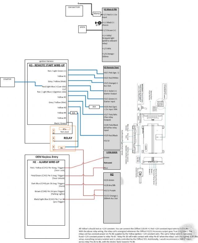
OK this may be hard to see but I think I have it!

Thanks - please double check.1996 ford bronco factory keyless entry? - Page 4 -- posted image.

CloudCasters
kreg357 
Platinum - Posts: 7,800
Platinum spaceThis member has made a donation to the12volt.com. Click here for more info.spaceThis member has been recognized as an authority in Electrical Theory. Click here for more info.spaceThis member has been recognized as an authority in Mobile Security and Convenience. Click here for more info.spacespace
Joined: January 30, 2009
Location: Pennsylvania, United States
Posted: February 08, 2013 at 7:09 PM / IP Logged  

A few minor things...

Clifford H3/2 RED / White should have a 30 Amp fuse in the wire ( not shown in diagram ).
Clifford H3/7 Pink/White should be OK with the factory default programming = IGN2
Not included on the diagram is the extra ACC2 relay coil quenching diode.

I'm guessing that the Clifford H1/5 White Parking Light is connected to the Bronco and working OK.

There are a few more wires not listed / shown that are important for the remote start portion of the install.

H2/2 BLACK/ WHITE (-) NEUTRAL SAFETY INPUT       to Chassis Ground   ** also install Neutral Safety Switch & set to ON
H2/16 BROWN (+) BRAKE SHUTD0WN INPUT   to Brake Wire    Light Green  (+)   @ brake pedal switch
H2/17 GREY (-) H00D PIN INPUT (N/C 0R N/0)   to hood pin supplied in Clifford kit
H2/23 VIOLET/WHITE TACHOMETER INPUT   Tachometer    Tan / YELLOW (AC)      @ at coil  ** Set Clifford to Engine Checking = Tach

Soldering is fun!
1966fskbk 
Member - Posts: 23
Member spacespace
Joined: February 02, 2013
Location: Washington, United States
Posted: February 08, 2013 at 8:05 PM / IP Logged  

I do not know where Im going ... but Im on my way!!!

I will update and repost... thanks so much folks!!!

I plan on finalizing / finishing everything this weekend...

Mike

CloudCasters
1966fskbk 
Member - Posts: 23
Member spacespace
Joined: February 02, 2013
Location: Washington, United States
Posted: February 08, 2013 at 11:12 PM / IP Logged  

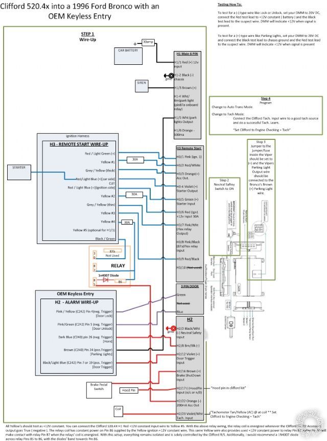
OK - the only thing I think Im missing is how to turn on the dome light?  I take it that this wire turns on dome?  Do I want to turn on dome?

H2/7 BLACK / YELLOW (-) 200mA DOME LIGHT SUPERVISION OUTPUT (One source I seen says connect to door trigger?) (Is door trigger pos.Trigger and wont that not work?)

1996 ford bronco factory keyless entry? - Page 4 -- posted image.

CloudCasters
kreg357 
Platinum - Posts: 7,800
Platinum spaceThis member has made a donation to the12volt.com. Click here for more info.spaceThis member has been recognized as an authority in Electrical Theory. Click here for more info.spaceThis member has been recognized as an authority in Mobile Security and Convenience. Click here for more info.spacespace
Joined: January 30, 2009
Location: Pennsylvania, United States
Posted: February 09, 2013 at 6:21 AM / IP Logged  

Dome Light Supervision is optional.  It is a nice feature but may not be necessary if the Cliffords'

Unlock command not only unlocks the doors but causes the dome light to turn on.  Most newer
vehicles have this built in.  Test to see if this happens.

Your Clifford unit outputs a (-) Dome Light Supervision signal.  The Bronco uses a (+) signal from the

door pin to indicate an open door ( an open door causes the Bronco to turn on the Dome Light ).  You
would need a relay to convert the Cliffords' (-) output to be acceptable / usable by the Bronco.  A 30/40
Amp SPDT relay would be used for this conversion and wired as below :
Relay Pin 85 to Clifford H2/7  BLACK / YELLOW (-) 200mA DOME LIGHT SUPERVISION OUTPUT 
Relay Pin 86 and 87 to Bronco Yellow #5 +12V constant fused at 10 Amps
Relay Pin 30 to Bronco All Door Trigger  BLACK/ LIGHT BLUE  (+)  @ DRIVER'S KICK PANEL
Relay Pin 87a not used - insulate ( or de-pin )

Soldering is fun!
1966fskbk 
Member - Posts: 23
Member spacespace
Joined: February 02, 2013
Location: Washington, United States
Posted: February 10, 2013 at 2:55 PM / IP Logged  
So this is fantastic!!! Everything worked first time!!! - Of course after setting feature 3 to "auto transmission" and putting in fuse located on the alarm brain, to correct + setting for lights.. oh yeah then doing tach learn.
A BIG Thanks to the12volt.com FORUM!! - this was a great learning experience, I have my entire wiring schematic above, know every connection is soldered taped and fused perfectly. I hope that the documentation in this thread will help anyone else needing to Clifford 520.4x installed. Big thanks to kreg357 and WEEN!
My Install Notes:   Everything is harnessed (black wire loom), I even used the factory firewall plug housing (pins that were vacant) to run the hood/pin, siren & tach through wires into the motor compartment area. I also made an insulated quick disconnect connector for the tach to alarm...in case the two need to separate in the future for motor repairs.
Last Question: I would love to now have the AUX button on my remote roll down the vehicles back window (only)for grocerie getting ease. How would I be able to do that
CloudCasters
Ween 
Platinum - Posts: 1,366
Platinum spacespace
Joined: August 01, 2004
Location: Illinois, United States
Posted: February 10, 2013 at 3:37 PM / IP Logged  
you'll need to locate the wire at the rear window switch that has power when the switch is pressed to the down position. did the same for my neighbor's bronco, can't remember the colors though. once you find the wire, you'll cut it to interrupt. wire as follows to additional relay:
term 87 and 86 ...battery power (fuse at same rating as rear window from factory...20A?)
term 87a ...down wire (switch side)
term 30 ...down wire (vehicle side)
term 85 ...aux output from remote starter (negative control)\
kreg357 
Platinum - Posts: 7,800
Platinum spaceThis member has made a donation to the12volt.com. Click here for more info.spaceThis member has been recognized as an authority in Electrical Theory. Click here for more info.spaceThis member has been recognized as an authority in Mobile Security and Convenience. Click here for more info.spacespace
Joined: January 30, 2009
Location: Pennsylvania, United States
Posted: February 10, 2013 at 5:04 PM / IP Logged  

Using a Clifford AUX output to roll down the back window might require a BitWriter to set the AUX

output duration to a fixed time period.    Measure the the number of seconds that it takes to roll down
the window and add 1 second, then use the BitWriter to program that time for the AUX output.

Another way is like Ween's also but uses a Directed 528T module, which has a 15 Amp relay built in

and can be set for any output duration from 1 to 90 seconds.   If you want  up and down check
out the Directed 529T module.

Soldering is fun!
Page of 5

  Printable version Printable version Post ReplyPost New Topic
You cannot post new topics in this forum
You cannot reply to topics in this forum
You cannot delete your posts in this forum
You cannot edit your posts in this forum
You cannot create polls in this forum
You cannot vote in polls in this forum

  •  
Search the12volt.com
Follow the12volt.com Follow the12volt.com on Facebook
Saturday, September 21, 2024 • Copyright © 1999-2024 the12volt.com, All Rights Reserved Privacy Policy & Use of Cookies
Disclaimer: *All information on this site ( the12volt.com ) is provided "as is" without any warranty of any kind, either expressed or implied, including but not limited to fitness for a particular use. Any user assumes the entire risk as to the accuracy and use of this information. Please verify all wire colors and diagrams before applying any information.

Secured by Sectigo
the12volt.com spacer
Support the12volt.com
Top
the12volt.com spacer