the12volt.com spacer
icon

Clifford Arrow 5 + Greddy Turbo Timer


Post ReplyPost New Topic
< Prev Topic Next Topic >
krayzie2k3 
Copper - Posts: 47
Copper spacespace
Joined: January 14, 2004
Location: United States
Posted: September 01, 2004 at 11:53 PM / IP Logged  

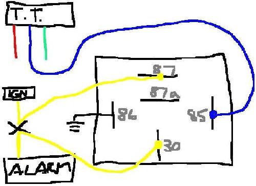
this is the best forum i can think to place this topic in. Clifford Arrow 5 + Greddy Turbo Timer -- posted image.

im assuming that i would use the accessory wire to a relay? thanks

profuse007 
Gold - Posts: 2,015
Gold spacespace
Joined: October 20, 2002
Location: Texas, United States
Posted: September 02, 2004 at 12:39 AM / IP Logged  
not sure what you want to do w/ the acc output wire, but yes, you do need a relay to output a proper (-) or (+) signal.
that wire usually used for channel 3 or most frequent, for trunk popper.
Houston,TX
"The two most common elements in the universe are H+ and stupidity" (Ellison).
krayzie2k3 
Copper - Posts: 47
Copper spacespace
Joined: January 14, 2004
Location: United States
Posted: September 02, 2004 at 10:39 AM / IP Logged  
what i wanted to do is install a turbo timer. have it set to 2 mins or so. but what i want is that when i get out of the car, hit the arm button on the remote and lock the doors.
krayzie2k3 
Copper - Posts: 47
Copper spacespace
Joined: January 14, 2004
Location: United States
Posted: September 09, 2004 at 10:11 PM / IP Logged  
any suggestions? basically i just wanna set it up where the car runs for like 2 minutes [aftermarket turbo timer], i get out of the car, arm the alarm [so the door locks]
cosmoworks 
Copper - Posts: 144
Copper spacespace
Joined: June 02, 2004
Location: United States
Posted: September 10, 2004 at 11:06 AM / IP Logged  
The problem is that you can't arm your car because ignition power is still supplied to your alarm by the turbo timer even with your key pulled out.
The trick to get the alarm to work is to have a relay break the igntion signal to your arrow 5 when the turbo timer is on. The Greddy timer has two outputs the blue and green wires (accesory and ignition respectively). You'll have to give up the ability of using accesory output while the turbo timer is keeping the engine running.
Instead of connecting the blue output wire from the turbo timer to the "acc" on the car, connect it to drive pin 85 on a stadard automotive relay. Connect pin 86 of the relay to ground. Then cut yellow wire coming out of your alarm (diagram you posted above). Connect the alarm side of the yellow wire to pin 30 on the relay, and connect the other side of the yellow wire (that previously went to the car's igntion or "on" wire to pin 87a on the relay.
The other option of turbo timing is to get rid of the turbo timer altogether and program the RED / white accesory output wire to a timed output and use it to run a relay to power the ignition for a set amount of time. Then before you turn your car off, just press the accesory output button of your remote before you shut the car off. Once again though, you'll need to use a relay to break the yellow ignition input wire to the alarm otherwise you wont be able to arm it as you're experiencing now.
krayzie2k3 
Copper - Posts: 47
Copper spacespace
Joined: January 14, 2004
Location: United States
Posted: September 11, 2004 at 12:14 AM / IP Logged  

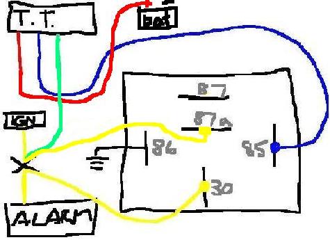
cosmoworks, this is my interpretation of what you told me. as far as accessory power, i could care less becuase when i park, shut off the car, all i want is the car to arm and lock the doors while the motor cools for a bit. what im curious is where would the red and green wire connect too? i am assuming that the red [12v] goes to the batt or tap iono the yellow? and the green ... ? thanks again.Clifford Arrow 5 + Greddy Turbo Timer -- posted image.

cosmoworks 
Copper - Posts: 144
Copper spacespace
Joined: June 02, 2004
Location: United States
Posted: September 11, 2004 at 5:48 PM / IP Logged  
Red goes directly to the battery, green goes to the ignition source (tapped in the same place as the yellow wire for your alarm... just remember to connect it to the key side of the car).
Your diagram otherwise is correct, EXCEPT change the key side of the ignition wire from pin 87 to 87a, since you want the circuit to be BROKEN when the turbo timer is outputting power otherwise you'll never be able to arm your car.
krayzie2k3 
Copper - Posts: 47
Copper spacespace
Joined: January 14, 2004
Location: United States
Posted: September 12, 2004 at 12:11 AM / IP Logged  

so connect the green and yellow together to the yellow on the ign side? im confused, earlier you said connect the alarm [yellow] to 87a and now i connect it to 87?  thanks again for your help.

cosmoworks wrote:
 connect the other side of the yellow wire (that previously went to the car's igntion or "on" wire to pin 87a on the relay. 

cosmoworks wrote:
change the key side of the ignition wire from pin 87 to 87a

krayzie2k3 
Copper - Posts: 47
Copper spacespace
Joined: January 14, 2004
Location: United States
Posted: September 12, 2004 at 12:12 AM / IP Logged  
this is what i came up with after reading the post.
krayzie2k3 
Copper - Posts: 47
Copper spacespace
Joined: January 14, 2004
Location: United States
Posted: September 12, 2004 at 12:13 AM / IP Logged  
hopefully this pic will work, dunno why the other one isnt working. Clifford Arrow 5 + Greddy Turbo Timer -- posted image.
Page of 3

  Printable version Printable version Post ReplyPost New Topic
You cannot post new topics in this forum
You cannot reply to topics in this forum
You cannot delete your posts in this forum
You cannot edit your posts in this forum
You cannot create polls in this forum
You cannot vote in polls in this forum

  •  
Search the12volt.com
Follow the12volt.com Follow the12volt.com on Facebook
Monday, April 29, 2024 • Copyright © 1999-2024 the12volt.com, All Rights Reserved Privacy Policy & Use of Cookies
Disclaimer: *All information on this site ( the12volt.com ) is provided "as is" without any warranty of any kind, either expressed or implied, including but not limited to fitness for a particular use. Any user assumes the entire risk as to the accuracy and use of this information. Please verify all wire colors and diagrams before applying any information.

Secured by Sectigo
the12volt.com spacer
Support the12volt.com
Top
the12volt.com spacer